In CINEMA 4D, you can modify the objects at an advanced level by converting them into editable polygons. The editable polygons consists of sub-objects that can be modified using the Move, Rotate, and Scale tools. The sub-objects are points, edges, and polygons. In this tutorial, you will learn to modify the objects at an advanced level by converting them into editable poly.
Step 1: Create a cylinder in the viewport using the Cylinder tool. Next, in the Attribute Manager, set the parameters as follows:
Height Segments: 100 Rotation segments: 100
Step 2: Make sure the Cylinder is selected in the Object Manager. In the Attribute Manager, choose the Caps button; the Caps area is displayed. In the Caps area, clear the Caps check box.
Step 3: Press C; the Cylinder is converted into a polygonal object.
Step 4: Choose the Polygons tool from the Modes Palette and select a polygon using the Live Selection tool and press CTRL+A; all the polygons of Cylinder get selected, as shown in Figure 1.
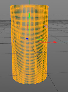 |
Figure 1
Step 5: Right-click on the selected polygons; a shortcut menu is displayed. Choose Reverse Normals from the shortcut menu; the normals of the selected polygons are reversed.
Step 6: Again, right-click on the selected polygons; a shortcut menu is displayed. Choose Extrude from the shortcut menu. In the Attribute Manager, set the parameters as follows:
Offset: 10 Var: 100
Next, clear the Preserve Groups check box and choose the Apply button in the Tool area. The polygons are extruded, as shown in Figure 2.
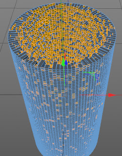 |
| Figure 2 |
Step 7: Right-click on the selected polygons; a shortcut menu is displayed. Choose Extrude Inner from the shortcut menu. In the Attribute Manager, enter 0.2 in the Offset spinner and clear the Preserve check box.
Step 8: Choose the Apply button in the Tool area. The polygons are extruded.
Step 9: Right-click on the selected polygons; a shortcut menu is displayed. Choose Extrude from the shortcut menu. In the Attribute Manager, enter 2 in the Offset spinner.
Step 10: In the Front viewport, using the B-Spline tool create a spline, as shown in Figure 3.
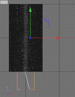 |
Figure 3
|
Step 11: In the Top viewport, create a circle using the Circle tool. In the Attribute Manager, enter 10 in the Radius spinner. Choose XY from the Plane drop-down list.
Step 12: Press and hold left mouse button on the HyperNURBS tool in the Command Palette; a flyout is displayed. Choose SweepNURBS from the flyout.
Step 13: Drag Spline to SweepNURBS in the Object Manager; the Spline is connected to SweepNURBS. Next, drag Circle to SweepNURBS; the Circle is connected to SweepNURBS, as shown in Figure 4.
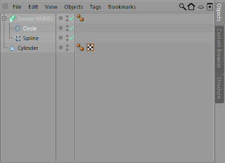 |
| Figure 4 |
Step 14: Press C; the SweepNURBS is converted into a polygonal object.
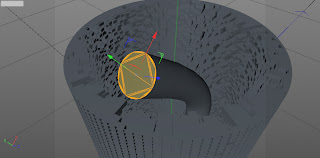
Step 15: Expand SweepNURBS in the Object Manager and select Cap 1 in it. Now, choose the Polygons tool from the Modes Palette and select a polygon using the Live Selection tool in the Perspective viewport, as shown in Figure 5. Delete the selected polygon.
 |
| Figure 5 |
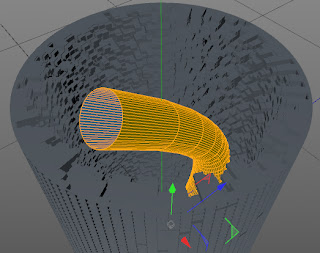
Step 16: Select the SweepNURBS in the Object Manager and make sure Polygons tool is selected from the Modes Palette. Select a polygon using the Live Selection tool and press CTRL+A; all the polygons of SweepNURBS get selected, as shown in Figure 6.
 |
| Figure 7 |
Step 17: Right-click on the selected polygons; a shortcut menu is displayed. Choose Extrude from the shortcut menu. In the Attribute Manager, enter 5 in the Offset spinner; the polygons are extruded.
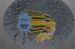
Step 18: Right-click on the selected polygons; a shortcut menu is displayed. Choose Extrude from the shortcut menu. In the Attribute Manager, choose the New Transform button in the Tool area, the polygons are extruded again, as shown in Figure 8.
 |
| Figure 8 |
Step 19: In the Material Manager, choose the Danel material.
Step 20: Change the color of Danel material to red in the Material Manager.
Step 21: Drag the Danel material to Cylinder in the Object Manager. The Danel material is applied to Cylinder in the Perspective viewport.
Step 22: In the Material Manager, choose the Danel material.
Step 23: Change the color of Danel material to brown in the Material Manager.
Step 24: Drag the Danel material to SweepNURBS in the Object Manager. The Danel material is applied to SweepNURBS in the Perspective viewport.
Step 25: Create a Spot Light in the Perspective viewport. In the Attribute Manager, choose the General button. In the General Properties area, set the parameters as follows:
R: 249 G: 149 B: 18
Step 26: In the General Properties area, select Shadow Maps (Soft) from the Shadow drop-down list. Next, select Volumetric from the Visible Light drop-down list.
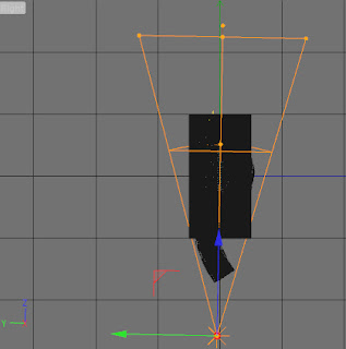
Step 27: In the Attribute Manager, choose the Details button. In the Details area, enter 31 in the Outer Angle spinner and place the Spot Light in the Right viewport, as shown in Figure 9.
 |
| Figure 9 |
Step 28: Create a Omni light in the Right viewport. In the Attribute Manager, choose the General button. In the General Properties area, set the parameters as follows:
R: 255 G: 222 B: 8
Step 29: In the Attribute Manager, choose the Visibility button. In the Visibility area, enter 12 in the Outer Distance spinner and enter 7 in the Inner Distance spinner.
Step 30: In the Attribute Manager, choose the Lens button. In the Lens area, select Hi-8 from the Glow drop-down list.
Step 31: Place the Omni light in the Right viewport, as shown in Figure 10.
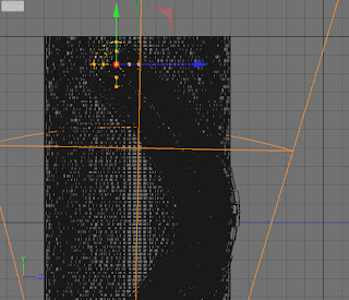 |
| Figure 10 |
Step 32: Choose Render Settings tool from the Command Palette; the Render Settings window will be displayed. In the Render Settings window, choose Effects button; a flyout will be displayed. Choose Ambient Occlusion and Global Illumination from it.
Step 33: Choose the Render to Picture Viewer tool from the Command Palette. The model is rendered in the Picture Viewer window, as shown in Figure 11.
 |
| Figure 11 |
|


No comments:
Post a Comment