Thinking Particles, the CINEMA 4D module is a node-based particle system and is used to control every aspect of particle motion. Using this module, we can emit particles, and collide particles with other particles and objects. Also, you can control aspects of lifelike forces such as gravity and wind.
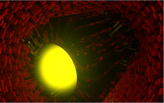
In this tutorial, you will create the puffy fire explosion effect in a scene, as shown in Figure 1 using the Thinking Particles module and XPresso Editor.
6. Select the Compare node in the XPresso Editor. In the Attribute Manager, choose the Node button; the Node Properties area is displayed. In this area, make sure Real option is selected in Data Type drop-down list and select <= from the Function drop-down list, refer to Figure 5.
7. In the Attribute Manager, choose the Parameter button; the Parameter area is displayed. In this area, 30 in the Input 2 spinner.
In this tutorial, you will create the puffy fire explosion effect in a scene, as shown in Figure 1 using the Thinking Particles module and XPresso Editor.
 |
| Figure 1 |
1. Choose Create > Object from the main menu; a cascading menu is displayed. Now, choose Null from it; a Null is added to the Object Manager. Rename Null as Fire Explosion.
2. In the Object Manager, right-click on Fire explosion; a shortcut menu is displayed. In this shortcut menu, choose CINEMA 4D Tags > XPresso; the XPresso Editor is displayed.
3. In the XPresso Editor, right-click in the empty space; a shortcut menu is displayed. In the shortcut menu, choose New Node > XPresso > General > Time, as shown in Figure 2; Time node is created in the XPresso Editor.
 |
| Figure 2 |
4. Double-click on the XPresso tag in the Object Manager; the XPresso Editor window is displayed. In this window, select the Time node and click on the red square; a flyout is displayed. Choose Frame from the flyout, as shown in Figure 3; the Frame port is added in the Time node.
 |
| Figure 3 |
5. In the XPresso Editor, right-click in the empty space; a shortcut menu is displayed. In the shortcut menu, choose New Node > XPresso > Logic > Compare, as shown in Figure 4; Compare node is created in the XPresso Editor.
 |
| Figure 4 |
 |
| Figure 5 |
8. Double-click on the XPresso tag in the Object Manager; the XPresso Editor window is displayed. In this window, right-click in the empty space; a shortcut menu is displayed. In the shortcut menu, choose New Node > Thinking Particles > TP Generator > PStorm, as shown in Figure 6; PStorm node is created in the XPresso Editor.
 |
| Figure 6 |
9. In the XPresso Editor, select the PStorm node and click on the blue square; a flyout is displayed. Choose On from the flyout, as shown in Figure 7; the On port is added in the PStorm node. Repeat the step and choose Emitter Alignment from the flyout; the Emitter Alignment port is added in the PStorm node.
 |
| Figure 7 |
10. Select the PStorm node in the XPresso Editor. In the Attribute Manager, choose the Parameter button; the Parameter area is displayed. In this area, select Rectangle option from the Type drop-down list and select Shot from the Birth Type drop-down list and set parameter as follows:
Life: 1000 Speed: 100 Size: 30
X Fov: 360 Y Fov: 360 X Size: 300
Y Size: 300
11. In the XPresso Editor, right-click in the empty space; a shortcut menu is displayed. In the shortcut menu, choose New Node > XPresso > General > Object; Fire explosion node is created in the XPresso Editor, as shown in Figure 8.
 |
| Figure 8 |
12. Select the Fire explosion node and click on the red square; a flyout is displayed. Choose Coordinates > Global Position > Global Position from the flyout; the Global Position port is added in the Fire explosion node.
13. In the XPresso Editor, select the Frame port of the Time node and press and hold the left mouse button and drag the cursor to the Input 1 port of the Compare node; the color of the wire turns green; the Frame port of the Time node is connected to the Input 1 port of the Compare node.
14. Select the Output port of the Compare node and press and hold the left mouse button and drag the cursor to the On port of the PStorm node; the color of the wire turns green; the Output port of the Compare node is connected to the On port of the PStorm node.
15. Select the Global Position port of the Fire explosion node and press and hold the left mouse button and drag the cursor to the Emitter Position port of the PStorm node; the color of the wire turns green and the Global Position port of the Fire explosion node is connected to the Emitter Position port of the PStorm node, as shown in Figure 9.
 |
| Figure 9 |
16. Choose Simulate > Thinking Particles from the main menu; a cascading menu is displayed. Now, choose Thinking Particles Settings from it, as shown in Figure 10; the Thinking Particles window is displayed.
 |
| Figure 10 |
17. In the Attribute Manager, make sure the Object button is chosen. In the Object Properties area, choose the arrow button next to the Particle Group field; the shape of the cursor changes. Now, select Fire in the Thinking Particles window; the Fire is added to the Particle Group field.
18. Double-click on the XPresso tag in the Object Manager; the XPresso Editor window is displayed. In this window, right-click in the empty space; a shortcut menu is displayed. In the shortcut menu, choose New Node > Thinking Particles > TP Initiator > P Pass; P Pass node is created in the XPresso Editor.
19. Select the PGroup node in the XPresso Editor. In the Attribute Manager, make sure the Parameter button is chosen. In the Parameter area, choose the arrow button next to the Group field; the shape of the cursor changes. Now, select Fire in the Thinking Particles window; the Fire is added to the P Pass node in the XPresso Editor.
20. In the XPresso Editor window, right-click in the empty space; a shortcut menu is displayed. In the shortcut menu, choose New Node > Thinking Particles > TP Dynamic > PGravity; PGravity node is created in the XPresso Editor.
21. Select the PGravity node in the XPresso Editor. In the Attribute Manager, make sure the Parameter button is chosen. In the Parameter area, choose the arrow button next to the Object field; the shape of the cursor changes. Now, select Fire explosion in the Object Manager; the Fire explosion is added to the PGravity node in the XPresso Editor. In the Attribute Manager, select the Spherical option from the Type drop-down list.
22. In the XPresso Editor window, select the P Pass node and connect the Fire port to the Fire explosion port of the PGravity node. Right-click on the empty space; a shortcut menu is displayed. In this shortcut menu, choose New Node > Thinking Particles > TP Helper > PGetData; PGetData node is created in the XPresso Editor.
23. Select the PGetData node and click on the red square; a flyout is displayed. Choose Position from the flyout; the Position port is added in the PGetData node. Right-click on the empty space; a shortcut menu is displayed. In this shortcut menu, choose New Node > XPresso > General > Object; Fire explosion node is created in the XPresso Editor.
24. Select the Fire explosion node and click on the red square; a flyout is displayed. Choose Coordiantes > Global Position > Global Position from the flyout; the Global Position port is added in the Fire explosion node.
25. In the XPresso Editor window, right-click on the empty space; a shortcut menu is displayed. In this shortcut menu, choose New Node > XPresso > Calculate > Math; Math node is created in the XPresso Editor. Select the Math node in the XPresso Editor. In the Attribute Manager, choose the Node button; the Node Properties area is displayed. In this area, select the Vector option from the Data Type drop-down list. Next, select Subtract option from the Function drop-down list.
26. In this window, select the PGetData node and connect the Position port of this node to the upper Input port of the Math: Subtract node. Figure 11 displays the Position port of PGetData node connected to the upper Input port of the of the Math: Subtract node.
 |
| Figure 11 |
27. Select the Fire explosion node and connect it to lower Input port of Math:Subtract node in the XPresso Editor. right-click on the empty space; a shortcut menu is displayed. In this shortcut menu, choose New Node > XPresso > Calculate > Range Mapper; Range Mapper node is created in the XPresso Editor.
28. Select the Range Mapper node in the XPresso Editor. In the Attribute Manager, choose the Parameter button; the Parameter area is displayed. In this area, set the parameters as follows:
Input Upper: 200 Output Lower: -600
Output Upper: -550
29. Double-click on the XPresso tag in the Object Manager; the XPresso Editor window is displayed. In this window, select the Math:Subtract node and connect the Output port to the Input port of the Range Mapper node.
30. Select the PGravity node and click on the blue square; a flyout is displayed. Choose Strength from the flyout; the Strength port is added in the PGravity node. Now, connect the Strength port of PGravity node to the Output port of the Range Mapper node.
31. Choose Create > Environment from the main menu; a cascading menu is displayed. Now, choose Environment from it; the Environment is added to the Object Manager.
32. Choose Create > Shader from the Material Manager’s main menu; a cascading menu is displayed. Now, choose PyroCluster from it, as shown in Figure 12 the PyroCluster material slot is created in Material Manager.
 |
| Figure 12 |
33. In the Material Manager, double-click on the PyroCluster; the Material Editor window is displayed. In this window, select Fire from the Settings drop-down list in the Globals area; the Cinema 4D Studio dialog box is displayed. In this dialog box, choose the Yes button; the fire effects settings are selected. Next, enter 10 in the Min spinner and 110 in the Max spinner. Now, close the window.
34. Select the Shape from the list displayed on the left of the Material Editor; the Shape area is displayed. In this area, enter 400 in the Radius spinner.
35. Choose Create > Shader from the Material Manager’s main menu; a cascading menu is displayed. Now, choose PyroCluster - VolumeTracer from it; the PyroCluster - VolumeTracer material slot is created in Material Manager.
36. Press and hold the left mouse button on PyroCluster - VolumeTracer in the Material Manager and drag the cursor to the Environment in the Object Manager; the PyroCluster - VolumeTracer is applied to Environment in the Object Manager, as shown in Figure 13.
 |
| Figure 13 |
37. Select the PyroCluster material slot is selected in Material Manager. Press and hold the left mouse button on it and drag the cursor to the Particle Geometry in the Object Manager; the PyroCluster is applied to Particle Geometry in the Object Manager.
