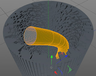
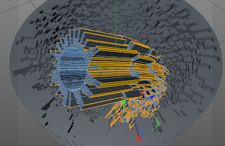
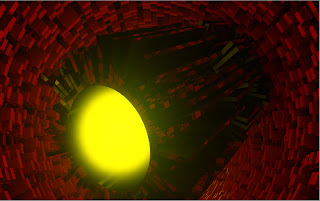
In this tutorial, you will create a vase using the Lather generator in CINEMA 4D.
This blog serves as an additional learning resource for and MAXON CINEMA 4D S24 Studio-A Tutorial Approach and book. It contains latest tutorials, articles, views, reviews, and tips and tricks on MAXON CINEMA 4D. A CADCIM Technologies, USA initiative.
Saturday, November 23, 2013
ct0008 - How to use the Loft generator?
In this tutorial, you will learn how to use the Loft generator to create a vase.
Saturday, June 8, 2013
ct0007 - Create fireworks using Tracer and Sketch & Toon shader
 |
| Figure 1 |
2. Choose Simulate > Particle > Emitter from the main menu; a Emitter is added to the Object Manager.
3. Make sure the Tracer is selected in the Object Manager. In the Attribute Manager, choose the Object button; the Object Properties area is displayed. In the Object Properties area, drag Emitter to the Trace Link, as shown in Figure 2.
Thursday, May 30, 2013
ct0006 - Creating vector art using MoSpline in Cinema 4D
In this tutorial, you will create vector art using MoSpline, shown in Figure 1.
 |
Figure 1
|
1. Choose Create > Spline from the main menu; a cascading menu is displayed. Now, choose Circle from it; a Circle is added to the Object Manager.
2. Choose MoGraph > MoSpline from the main menu; a MoSpline is added to the Object Manager.
2. Choose MoGraph > MoSpline from the main menu; a MoSpline is added to the Object Manager.
3. Make sure the MoSpline is selected in the Object Manager. In the Attribute Manager, choose the Object button; the Object Properties area is displayed. In the Object Properties area, enter -12.5 in the Offset spinner and enter 85.1 in the Start spinner.
4. Make sure the MoSpline is selected in the Object Manager. In the Attribute Manager,choose the Simple button; the Simple area is displayed. In the Simple area, set the parameters as follows:
Length: 5831 Segments: 56 Angle H: 176
Angle P: 271 Angle B: 360 Curve: -143
Bend: -87 Twist: 360 Width: 1.5
After entering these values MoSpline is displayed, as shown in Figure 2.
Wednesday, May 22, 2013
ct0005 - Creating animation using MoGraph and Softbody Dynamics
The Dynamics Body tag consists the object-relevant properties of both the Rigid
and Soft Bodies and is the most important control element for
Dynamics. In this tutorial, you will create motion graphics animation, shown in Figure 1.
1. Choose Create > Object from the main menu; a cascading menu is displayed. Now, choose Sphere from it; a Sphere is added to the Object Manager.
8. In the Object Manager, select Sphere and then drag it to Cloner; the Sphere is connected to Cloner. Also, clones of Sphere are created in the Perspective viewport, as shown in Figure 2.
 |
| Figure 1 |
2. Make sure the Sphere is selected in the Object Manager. In the Attribute Manager, choose the Object button; the Object Properties area is displayed. In the Object Properties area, enter 10 in the Radius spinner.
3. Choose Create > Spline from the main menu; a cascading menu is displayed. Now, choose Circle from it; a Circle is added to the Object Manager. In the Object Properties area, select XZ from the Plane drop-down list.
4. Choose MoGraph > Cloner from the main menu; a Cloner is added to the Object Manager.
5. Create a cloner using the Cloner tool. In the Attribute Manager, select Object from the Mode drop-down list.
6. Make sure that Cloner is selected in the Object Manager. In the Attribute Manager, choose the arrow button next to the Object text box and select Circle in the Object Manager. The Circle object is added to Object text box.
7. Make sure that Cloner is selected in the Object Manager. In the Attribute Manager, enter 450 in the Count spinner.
Wednesday, May 15, 2013
Coming Soon - Abstract Animation C4D Tutorial
Animation created using MoGraph and Softbody Dynamics
Stay tuned !!!
Stay tuned !!!
Special of the month - Avail 50 % discount
Avail 50% discount on the following textbooks:
Adobe Premiere Pro CS6 - A Tutorial Approach
Adobe Flash Professional CS6 - A Tutorial Approach
The eyeon Fusion 6.3 - A Tutorial Approach
Now that’s some good deal to crack!
Maxon Cinema 4D Studio R14 Book
Maxon Cinema 4D Studio R14 Book aims at harnessing the power of MAXON CINEMA 4D R14 Studio for modelers, animators, and designers. The Maxon Cinema 4D Studio R14 Book caters to the needs of both the novice and the advance users of MAXON CINEMA 4D R14 Studio. Keeping in view the varied requirements of users, the textbook first introduces the basic features of CINEMA 4D R14 Studio and then progresses to cover the advanced techniques. In this textbook, two projects based on the tools and concepts covered in the book have been added to enhance the knowledge of users. This textbook will help you unleash your creativity and transform your imagination into reality with ease.
Use code cgs2013 to get $4 discount:
Buy Maxon Cinema 4D Studio R14 Book Now
Sunday, May 12, 2013
ct0004 - Create abstract flower shape using animated growing splines in CINEMA 4D
The MoSpline is a Spline generator with which you can grow flower-like spline shapes and animate growing splines. In this tutorial, you will create motion graphics, shown in Figure 1 using Mospline.
1. Choose Create > Spline from the main menu; a cascading menu is displayed. Now, choose Circle from it; a Circle is added to the Object Manager.
6. Choose Create > NURBS from the main menu; a cascading menu is displayed. Now, choose Sweep NURBS from it; a Sweep NURBS is added to the Object Manager.
16. Double-click in the Material Manager; a new shader with the name Mat is created in the Material Manager. Select the shader; the Material Editor is displayed. In the Color area, set the parameters as follows:
 |
| Figure 1 |
2. Make sure the Circle is selected in the Object Manager. In the Attribute Manager, choose the Object button; the Object Properties area is displayed. In the Object Properties area, enter 5 in the Radius spinner.
3. Choose MoGraph > MoSpline from the main menu; a MoSpline is added to the Object Manager.
4. Make sure the MoSpline is selected in the Object Manager. In the Attribute Manager,choose the Object button; the Object Properties area is displayed. In the Object Properties area, enter 0.7 in the Offset spinner and clear the Extend End check box.
5. Make sure the MoSpline is selected in the Object Manager. In the Attribute Manager,choose the Simple button; the Simple area is displayed. In the Simple area, set the parameters as follows:
Length: 1086 Steps: 24 Segments: 100
Angle H: 198 Angle P: 183 Angle P: 182
Curve: 129 Bend: 48 Twist: 50
Width: 3.19
After entering these values MoSpline is displayed, as shown in Figure 2.
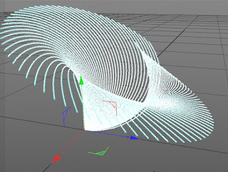 |
| Figure 2 |
7. Make sure that MoSpline is selected in the Object Manager. Press and hold the left mouse button on MoSpline and drag the cursor to Sweep NURBS in the Object Manager; the MoSpline is connected to Sweep NURBS in the Object Manager. Similarly, drag Circle to Sweep NURBS in the Object Manager; the Circle is connected to Sweep NURBS in the Object Manager.
8. Select MoSpline in the Object Manager. Choose MoGraph > Effector > Random; Random is added to the Object Manager.
9. Select Random in the Object Manager. Choose the Parameter button. Expand the Transform area, clear the Position check box and select the Scale check box. Next, enter 0.38 in the S . Y spinner. Next, enter 0.45 in the S . Z spinner.
10. In the Transform area, select the Rotate check box and enter 36 in the R . H spinner and 6 in the R . P spinner.
11. Choose Create > Light > Light from from the main menu; a light is added to the Object Manager.
12. Make sure that Light is selected in the Object Manager. In the Object Manager, choose the General button. In the General area, select Shadow Maps (Soft) from the Shadow drop-down list and Volumetric from the Visible Light drop-down list.
13. Choose the Visibility button. In the Visibility area, enter 25 in the Outer Distance spinner. Choose the Lens button in the Attribute Manager and select Candle from the Glow drop-down list.
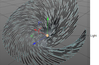
14. Now, invoke the Move tool and place the Light in center of the MoSpline in the Perspective viewport, as shown in
Figure 3.
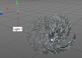
15. Choose Create > Light > Light from from the main menu; a Light.1 is added to the Object Manager. place the Light on the top of the MoSpline, as shown in Figure 4.
12. Make sure that Light is selected in the Object Manager. In the Object Manager, choose the General button. In the General area, select Shadow Maps (Soft) from the Shadow drop-down list and Volumetric from the Visible Light drop-down list.
13. Choose the Visibility button. In the Visibility area, enter 25 in the Outer Distance spinner. Choose the Lens button in the Attribute Manager and select Candle from the Glow drop-down list.
14. Now, invoke the Move tool and place the Light in center of the MoSpline in the Perspective viewport, as shown in
Figure 3.
 |
| Figure 3 |
 |
| Figure 4 |
R: 143 G: 34 B: 197
17. In the Material Editor, select the Reflection check box; the Reflection area is displayed. In the Reflection area, enter 46 in the Brightness spinner.
18. Make sure the Mat is selected in the Material Manager. Drag and drop the Mat shader on the MoSpline in the Object Manager; the Mat is applied to the MoSpline.
19. Choose the Render to Picture Viewer button from the Command Palette; the rendering takes place in the Picture Viewer window.
Tuesday, April 30, 2013
ct0003 - Create puffy fire explosion in Cinema 4D
Thinking Particles, the CINEMA 4D module is a node-based particle system and is used to control every aspect of particle motion. Using this module, we can emit particles, and collide particles with other particles and objects. Also, you can control aspects of lifelike forces such as gravity and wind.
In this tutorial, you will create the puffy fire explosion effect in a scene, as shown in Figure 1 using the Thinking Particles module and XPresso Editor.
6. Select the Compare node in the XPresso Editor. In the Attribute Manager, choose the Node button; the Node Properties area is displayed. In this area, make sure Real option is selected in Data Type drop-down list and select <= from the Function drop-down list, refer to Figure 5.
7. In the Attribute Manager, choose the Parameter button; the Parameter area is displayed. In this area, 30 in the Input 2 spinner.
In this tutorial, you will create the puffy fire explosion effect in a scene, as shown in Figure 1 using the Thinking Particles module and XPresso Editor.
 |
| Figure 1 |
1. Choose Create > Object from the main menu; a cascading menu is displayed. Now, choose Null from it; a Null is added to the Object Manager. Rename Null as Fire Explosion.
2. In the Object Manager, right-click on Fire explosion; a shortcut menu is displayed. In this shortcut menu, choose CINEMA 4D Tags > XPresso; the XPresso Editor is displayed.
3. In the XPresso Editor, right-click in the empty space; a shortcut menu is displayed. In the shortcut menu, choose New Node > XPresso > General > Time, as shown in Figure 2; Time node is created in the XPresso Editor.
 |
| Figure 2 |
4. Double-click on the XPresso tag in the Object Manager; the XPresso Editor window is displayed. In this window, select the Time node and click on the red square; a flyout is displayed. Choose Frame from the flyout, as shown in Figure 3; the Frame port is added in the Time node.
 |
| Figure 3 |
5. In the XPresso Editor, right-click in the empty space; a shortcut menu is displayed. In the shortcut menu, choose New Node > XPresso > Logic > Compare, as shown in Figure 4; Compare node is created in the XPresso Editor.
 |
| Figure 4 |
 |
| Figure 5 |
8. Double-click on the XPresso tag in the Object Manager; the XPresso Editor window is displayed. In this window, right-click in the empty space; a shortcut menu is displayed. In the shortcut menu, choose New Node > Thinking Particles > TP Generator > PStorm, as shown in Figure 6; PStorm node is created in the XPresso Editor.
 |
| Figure 6 |
9. In the XPresso Editor, select the PStorm node and click on the blue square; a flyout is displayed. Choose On from the flyout, as shown in Figure 7; the On port is added in the PStorm node. Repeat the step and choose Emitter Alignment from the flyout; the Emitter Alignment port is added in the PStorm node.
 |
| Figure 7 |
10. Select the PStorm node in the XPresso Editor. In the Attribute Manager, choose the Parameter button; the Parameter area is displayed. In this area, select Rectangle option from the Type drop-down list and select Shot from the Birth Type drop-down list and set parameter as follows:
Life: 1000 Speed: 100 Size: 30
X Fov: 360 Y Fov: 360 X Size: 300
Y Size: 300
11. In the XPresso Editor, right-click in the empty space; a shortcut menu is displayed. In the shortcut menu, choose New Node > XPresso > General > Object; Fire explosion node is created in the XPresso Editor, as shown in Figure 8.
 |
| Figure 8 |
12. Select the Fire explosion node and click on the red square; a flyout is displayed. Choose Coordinates > Global Position > Global Position from the flyout; the Global Position port is added in the Fire explosion node.
13. In the XPresso Editor, select the Frame port of the Time node and press and hold the left mouse button and drag the cursor to the Input 1 port of the Compare node; the color of the wire turns green; the Frame port of the Time node is connected to the Input 1 port of the Compare node.
14. Select the Output port of the Compare node and press and hold the left mouse button and drag the cursor to the On port of the PStorm node; the color of the wire turns green; the Output port of the Compare node is connected to the On port of the PStorm node.
15. Select the Global Position port of the Fire explosion node and press and hold the left mouse button and drag the cursor to the Emitter Position port of the PStorm node; the color of the wire turns green and the Global Position port of the Fire explosion node is connected to the Emitter Position port of the PStorm node, as shown in Figure 9.
 |
| Figure 9 |
16. Choose Simulate > Thinking Particles from the main menu; a cascading menu is displayed. Now, choose Thinking Particles Settings from it, as shown in Figure 10; the Thinking Particles window is displayed.
 |
| Figure 10 |
17. In the Attribute Manager, make sure the Object button is chosen. In the Object Properties area, choose the arrow button next to the Particle Group field; the shape of the cursor changes. Now, select Fire in the Thinking Particles window; the Fire is added to the Particle Group field.
18. Double-click on the XPresso tag in the Object Manager; the XPresso Editor window is displayed. In this window, right-click in the empty space; a shortcut menu is displayed. In the shortcut menu, choose New Node > Thinking Particles > TP Initiator > P Pass; P Pass node is created in the XPresso Editor.
19. Select the PGroup node in the XPresso Editor. In the Attribute Manager, make sure the Parameter button is chosen. In the Parameter area, choose the arrow button next to the Group field; the shape of the cursor changes. Now, select Fire in the Thinking Particles window; the Fire is added to the P Pass node in the XPresso Editor.
20. In the XPresso Editor window, right-click in the empty space; a shortcut menu is displayed. In the shortcut menu, choose New Node > Thinking Particles > TP Dynamic > PGravity; PGravity node is created in the XPresso Editor.
21. Select the PGravity node in the XPresso Editor. In the Attribute Manager, make sure the Parameter button is chosen. In the Parameter area, choose the arrow button next to the Object field; the shape of the cursor changes. Now, select Fire explosion in the Object Manager; the Fire explosion is added to the PGravity node in the XPresso Editor. In the Attribute Manager, select the Spherical option from the Type drop-down list.
22. In the XPresso Editor window, select the P Pass node and connect the Fire port to the Fire explosion port of the PGravity node. Right-click on the empty space; a shortcut menu is displayed. In this shortcut menu, choose New Node > Thinking Particles > TP Helper > PGetData; PGetData node is created in the XPresso Editor.
23. Select the PGetData node and click on the red square; a flyout is displayed. Choose Position from the flyout; the Position port is added in the PGetData node. Right-click on the empty space; a shortcut menu is displayed. In this shortcut menu, choose New Node > XPresso > General > Object; Fire explosion node is created in the XPresso Editor.
24. Select the Fire explosion node and click on the red square; a flyout is displayed. Choose Coordiantes > Global Position > Global Position from the flyout; the Global Position port is added in the Fire explosion node.
25. In the XPresso Editor window, right-click on the empty space; a shortcut menu is displayed. In this shortcut menu, choose New Node > XPresso > Calculate > Math; Math node is created in the XPresso Editor. Select the Math node in the XPresso Editor. In the Attribute Manager, choose the Node button; the Node Properties area is displayed. In this area, select the Vector option from the Data Type drop-down list. Next, select Subtract option from the Function drop-down list.
26. In this window, select the PGetData node and connect the Position port of this node to the upper Input port of the Math: Subtract node. Figure 11 displays the Position port of PGetData node connected to the upper Input port of the of the Math: Subtract node.
 |
| Figure 11 |
27. Select the Fire explosion node and connect it to lower Input port of Math:Subtract node in the XPresso Editor. right-click on the empty space; a shortcut menu is displayed. In this shortcut menu, choose New Node > XPresso > Calculate > Range Mapper; Range Mapper node is created in the XPresso Editor.
28. Select the Range Mapper node in the XPresso Editor. In the Attribute Manager, choose the Parameter button; the Parameter area is displayed. In this area, set the parameters as follows:
Input Upper: 200 Output Lower: -600
Output Upper: -550
29. Double-click on the XPresso tag in the Object Manager; the XPresso Editor window is displayed. In this window, select the Math:Subtract node and connect the Output port to the Input port of the Range Mapper node.
30. Select the PGravity node and click on the blue square; a flyout is displayed. Choose Strength from the flyout; the Strength port is added in the PGravity node. Now, connect the Strength port of PGravity node to the Output port of the Range Mapper node.
31. Choose Create > Environment from the main menu; a cascading menu is displayed. Now, choose Environment from it; the Environment is added to the Object Manager.
32. Choose Create > Shader from the Material Manager’s main menu; a cascading menu is displayed. Now, choose PyroCluster from it, as shown in Figure 12 the PyroCluster material slot is created in Material Manager.
 |
| Figure 12 |
33. In the Material Manager, double-click on the PyroCluster; the Material Editor window is displayed. In this window, select Fire from the Settings drop-down list in the Globals area; the Cinema 4D Studio dialog box is displayed. In this dialog box, choose the Yes button; the fire effects settings are selected. Next, enter 10 in the Min spinner and 110 in the Max spinner. Now, close the window.
34. Select the Shape from the list displayed on the left of the Material Editor; the Shape area is displayed. In this area, enter 400 in the Radius spinner.
35. Choose Create > Shader from the Material Manager’s main menu; a cascading menu is displayed. Now, choose PyroCluster - VolumeTracer from it; the PyroCluster - VolumeTracer material slot is created in Material Manager.
36. Press and hold the left mouse button on PyroCluster - VolumeTracer in the Material Manager and drag the cursor to the Environment in the Object Manager; the PyroCluster - VolumeTracer is applied to Environment in the Object Manager, as shown in Figure 13.
 |
| Figure 13 |
37. Select the PyroCluster material slot is selected in Material Manager. Press and hold the left mouse button on it and drag the cursor to the Particle Geometry in the Object Manager; the PyroCluster is applied to Particle Geometry in the Object Manager.
Monday, April 8, 2013
ct0002- Creating Greebels
In CINEMA 4D, you can modify the objects at an advanced level by converting them into editable polygons. The editable polygons consists of sub-objects that can be modified using the Move, Rotate, and Scale tools. The sub-objects are points, edges, and polygons. In this tutorial, you will learn to modify the objects at an advanced level by converting them into editable poly.
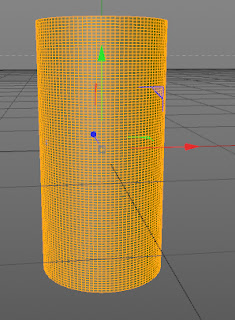
Step 1: Create a cylinder in the viewport using the Cylinder tool. Next, in the Attribute Manager, set the parameters as follows:
Height Segments: 100 Rotation segments: 100
Step 2: Make sure the Cylinder is selected in the Object Manager. In the Attribute Manager, choose the Caps button; the Caps area is displayed. In the Caps area, clear the Caps check box.
Step 3: Press C; the Cylinder is converted into a polygonal object.
Step 4: Choose the Polygons tool from the Modes Palette and select a polygon using the Live Selection tool and press CTRL+A; all the polygons of Cylinder get selected, as shown in Figure 1.
Subscribe to:
Posts (Atom)


